In nature, nothing is perfect and everything is perfect. Trees can be contorted, bent in weird ways, and they're still beautiful.
—Alice Walker
Recently, I've been working with the Device Tree format, which is becoming widely used for automatically configuring the hardware of embedded computing platforms like the Beaglebone Black, Xilinx Zynq, Altera Arria, and many other System-on-Chip (SOC) devices. The Device Tree is read during the computing platform boot up sequence, and it describes all the hardware of the embedded computing platform. It contains descriptions of all the platform parameters, like how much memory, what kind of interfaces, how many peripherals, etc. are expected to be present in that make and model of platform. In this article, I'll introduce the Device Tree format, and discuss how it is being used on current embedded computing platforms.
What are Device Trees?
A Device Tree is a data structure for describing the heirarchy of hardware subsystems within a computing platform, or an add-on peripheral to that platform. It can be used to automatically select and configure the device drivers for that computing platform. A Device Tree can be represented in several formats, such as the human readable "Device Tree Source" format, or the compact, binary, "Flattened Device Tree" format.
Why Device Tree?
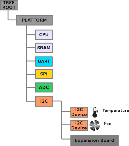 As many new and different System-on-Chip (SOC) based embedded computing platforms started appearing a few years ago,
it became increasingly difficult to support all the various operating system configurations required
for Linux, IOS, Windows, and others.
Prior to the adoption of the Device Tree format, this platform information was contained in what is known as the Board Support Package (BSP), a group of files provided by the manufacturer of that particular board. Each new operating system version would need to include the hardware configuration information from the Board Support Package (BSP) in order to be able to run on that particular board. This quickly became a bottleneck in the process of supporting new computing platforms that had only minor variations, so Linus Torvalds and others needed to push back, and come up with a more dynamic method of describing the hardware of the computing platform.
The Device Tree format was adopted to serve as the container format for hardware configuration information required during the boot process, however a way was still needed to modify the system after the boot up process, and to support expansion boards and subsystems. Pantelis Antoniu, Grant Likely, and others have outlined a solution that allows for Device Tree Overlays, and an expansion board (Cape) manager to modify the Device Tree from user-space, during run-time. This allows users to load and unload hardware peripherals and drivers as needed. The transition away from solely using Board Support Package (BSP) files to the Device Tree format is ongoing, and not without it's share of problems.
Embedded Device Trees
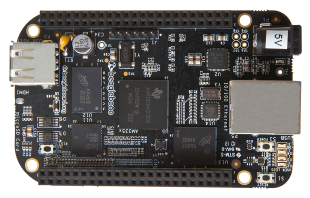
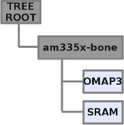
So, what is an embedded device tree, and how do we describe it? Let's look at a common example, say the BeagleBone Black, which uses an OMAP3 System-on-Chip from Texas Instruments. A very (very) simplified example, including just the CPU and it's main memory, would look something like this :
|
|
The corresponding Device Tree Source (.dts) file for the above would look something like :
1
2
3
4
5
6
7
8
9
10
11
12
13
14
15
16
{
        model      = "TI AM335x BeagleBone Black";
        compatible = "ti,beaglebone-black",
                     "ti,am335x-boneblack",
                     "ti,am335x-bone",
                     "ti,am33xx";
        cpus {
                cpu@0 {
                       cpu0-supply = <&dcdc2_reg>;
                };
        };
        memory {
                device_type = "memory";
                reg = <0x80000000 0x10000000>; /* 256 MB */
        };
};
As we can see from the above Device Tree Source (.dts) example, we have defined the following :
- model : defines the model name of this board
- compatible : defines the manufacturer & model compatibility list
- cpus : defines a single cpu with a node name of "cpu", and what power supply it uses
- memory : defines 256 MegaBytes of main memory on this model, and it's address range
Next we'll add some input/output to the Device Tree Source (.dts) file, and we'll start with a simple I2C controller
in order to create a tiny, but useful little computing platform description :
1
2
3
4
5
6
7
8
9
10
11
12
13
14
15
16
17
18
19
20
21
22
23
24
25
26
27
28
29
30
31
32
33
34
35
36
37
38
{
        model      = "TI AM335x BeagleBone Black";
        compatible = "ti,beaglebone-black",
                     "ti,am335x-boneblack",
                     "ti,am335x-bone",
                     "ti,am33xx";
        cpus {
                cpu@0 {
                       cpu0-supply = <&dcdc2_reg>;
                };
        };
        memory {
                device_type = "memory";
                reg = <0x80000000 0x10000000>; /* 256 MB */
        };
        am33xx_pinmux: pinmux@44e10800 {
		pinctrl-names = "default";
		pinctrl-0 = <&clkout2_pin>;
		i2c0_pins: pinmux_i2c0_pins {
			pinctrl-single,pins = <
                                /* i2c0_sda.i2c0_sda pin */
				0x188 (PIN_INPUT_PULLUP | MUX_MODE0)
				/* i2c0_scl.i2c0_scl */
				0x18c (PIN_INPUT_PULLUP | MUX_MODE0)
			>;
		};
        };
        ocp {
		i2c0: i2c@44e0b000 {
			pinctrl-names = "default";
			pinctrl-0 = <&i2c0_pins>;
			status = "okay";
			clock-frequency = <400000>;
			tps: tps@24 {
				reg = <0x24>;
			};
        };
};
The first thing we added above is the I/O Pin Multiplexing defintions, as most modern System-on-Chip (SoC) devices have several functions available per pin for application flexibility. We need to define what pins are going to be used to connect the I2C controller to the outside world.
- am33xx_pinmux: the label for the pin multiplexing control registers (pinmux) at address 0x44e10800
- i2c0_pins : the label for the pins assigned to the I2C Controller at offsets 0x188 and 0x18C
The next section defines the I2C controller itself, which is located on the OCP bus (Open Core Protocol) which is the name for one of internal bus connections in the System-on-Chip (SoC):
- i2c0: the label for the first I2C controller block at address 0x44e0b000
- status: we expect the I2C controller block status to be operational
- clock-frequency: the I2C bus is running at 400Khz
And finally, we describe a sub-node of the I2C controller (i.e. an attached I2C device), called "tps":
(this is a "subnode" or indirect address)
Alright, now we need to define the "tps" node to make this a more complete Device Tree Source (.dts) file,
which allows me to introduce the concept of power supply descriptions. It is really useful to know how much power that the power supplies on
a board are capable of providing, and what additional power that expansion devices or add-on boards will require.
That will allow us to indicate an error if an expansion device requires more power than we are capable of providing.
1
2
3
4
5
6
7
8
9
10
11
12
13
14
15
16
17
18
19
20
21
22
23
24
25
26
/include/ "tps65217.dtsi"
&tps {
	regulators {
		dcdc1_reg: regulator@0 {
			regulator-always-on;
		};
		dcdc2_reg: regulator@1 {
			regulator-name = "vdd_mpu";
			regulator-min-microvolt = <925000>;
			regulator-max-microvolt = <1325000>;
			regulator-boot-on;
			regulator-always-on;
		};
		dcdc3_reg: regulator@2 {
			regulator-name = "vdd_core";
			regulator-min-microvolt = <925000>;
			regulator-max-microvolt = <1150000>;
			regulator-boot-on;
			regulator-always-on;
		};
		ldo1_reg: regulator@3 {
			regulator-always-on;
		};

	};
};
In the above example, you'll start to see the use of Device Tree Source Include files (.dtsi), which allow us to include subnode definitions by model name, for building heirarchically. You'll also notice the defintion of the "dcdc2_reg" label here, which was used in our first example to define the power supply for the cpu. A few of the parameters worth mentioning:
- regulator-min-microvolt: how we define the min/max range of the power supplies
- regulator-boot-on: this regulator is on during booting
- regulator-always-on: this regulator is expected to be always powered up
Installing the Device Tree Compiler
On a typical Linux system distribution, you can install the Device Tree compiler using :sudo apt-get install -y device-tree-compilermoxon@fs:~$ dtc -v
Version: DTC 1.3.0
moxon@fs:~$
Using the Device Tree Compiler
The Device Tree Compiler is a simple command line tool that is used to read Device Tree Source (.dts) files, and generate a Flattened Device Tree Binary Object file (.dtb), also known as the "Device Tree BLOB".moxon@fs:~$ dtc -O dtb -o outputBLOB.dtb -b 0 inputSOURCE.dts
Flattened Device Tree Binary Objects (.dtb)
So what does the output of the Device Tree Compiler look like? If you want the gory details(including the address alignment requirements), they are described in Chapter 8 of the ePAPR specification, but here's a quick overview :
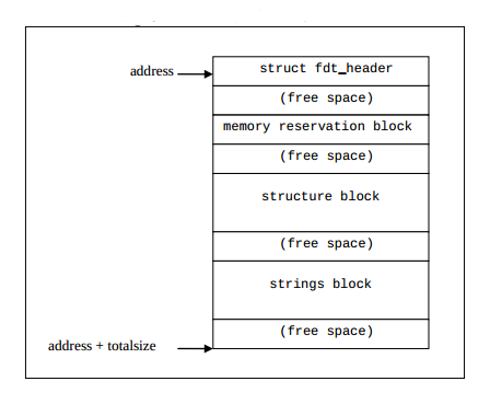
And the Flattened Device Tree Binary Header Structure (fdt_header) looks like this :
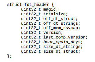
After the Flattened Device Tree Binary Header Structure, comes the memory reservation block, the structure block, and the strings block, respectively. So the Flattened Device Tree Binary format is not that complicated to understand, and the main "action" occurs by parsing the "structure" block, which holds the node relationships (i.e. the graph of the tree). The structure block is a list of nodes, separated by the following tokens to give the tree it's structure :
- 0x00000001 : FDT_BEGIN_NODE : Starts a node description, with node name and address as strings
- 0x00000002 : FDT_END_NODE : Ends a node description
- 0x00000003 : FDT_PROP : Starts a node property, followed by a node property structure
- 0x00000003 : FDT_NOP : No Operation, used as a placeholder and alignment filler
- 0x00000003 : FDT_END : Ends the structure block, only one per Device Tree.
In the next article, I'll cover Device Tree Overlays, the new mechanism for describing the hardware of add-on boards like BeagleBone "Capes", or Raspberry Pi "Plates".
References, Footnotes, and more Device Tree information...
- Device Tree for Dummies - Thomas Petroni
- BeagleBlack Device Tree Tutorial - Adafruit
- Xilinx Device Tree Tutorial - Xillybus
- Altera Device Tree Tutorial - Xillybus
- ARM Device Tree Support - Ubuntu
- Altera Device Tree Support - Altera
- Index of Device Tree Bindings - kernal.org
- Device Tree Graphing - kernal.org
- libfdt - manipulating FDT Blobs - David Gibson
- Linux Bootloaders - informit.com
- Device Tree PnP - Eli Billauer
- Device Tree Overlay Manager - Pantelis Antoniou
- Device Tree Overlay Proposal - Grant Likely
- BeagleBlack Univeral I/O - cdsteinkuehler
- BeagleBlack Device Tree Overlay Generator - Kilobaser
- GPIOs on the Beaglebone Black using the Device Tree Overlays- derek molloy
- Supporting 200 Different Expansion Boards - elinux.org
- DT, The Disaster so Far - Mark Rutland
- Board File to Device Tree Migration - Pantelis Antoniou